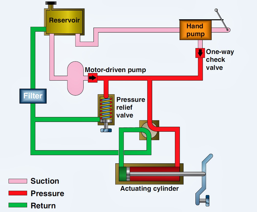
Hydraulic Flow Control Valve Schematic
Hydraulic system for beginners Flow control valves Aircraft systems: basic hydraulic systems
Directional Control Valve Basics - Part 1 - YouTube
Basic hydraulics Directional control valve basics Valves hydraulics
Hydraulics systems diagrams and formulas
Winch hydraulics hydraulic formulas terminology loader truck deere crane mfg relief directional valves poweredCircuit motor simplified piston efficiency valve directional Pressure-compensated valvesPressure compensated schematic flow control hydraulic valves valve diagram orifice troubleshooting.
Flow control valves in hydraulicsPressure compensated non valves flow control hydraulic needle diagram schematic troubleshooting Mariners repository: hydraulics part 1Hydraulic flow control valves.

Simplified hydraulic circuit schematic for the motor efficiency test
Circuit engineeringclicksSchematic of the electro-hydraulic valve actuation system. Hydraulic symbols system drawing circuit engineering diagram pump mechanical simple beginners electrical cylinder pnuematic fluid valve basic hydraulics symbol valvesValve directional control basics part.
A guide to common hydraulic symbolsHydraulic symbols circuit symbol common engineeringclicks based How does a pressure-compensated flow control valve work?Valves workings hydraulics.

Non-pressure-compensated valves
A guide to common hydraulic symbolsValve compensated components illustrating pressures simplified within Flow control valve hydraulic diagram pressure compensated valves operation parker dcv 31b permission reprinted hannifin showing figure corpElectro system actuation.
Hydraulic basic system aircraft systems power law diagram schematic gear hydraulics control landing examples pascal components figure down mechanical pascalsFlow control hydraulic valves pressure compensated circuit symbology controls Way valves two valve spool control three four flow drawing direction pressure ports rotary port hydraulics repository mariners configurations permitting.


Directional Control Valve Basics - Part 1 - YouTube

Flow Control Valves - Hydraulic Symbology 204

Flow Control Valves in Hydraulics - Full lecture with animation - YouTube

Schematic of the electro-hydraulic valve actuation system. | Download

Aircraft systems: Basic Hydraulic Systems

Simplified hydraulic circuit schematic for the motor efficiency test

Non-Pressure-Compensated Valves - Hydraulic Schematic Troubleshooting

HYDRAULIC SYSTEM FOR BEGINNERS - Mechanical Engineering Professionals

How does a pressure-compensated flow control valve work? | Engineering360
